
This article will examine the 8086 microprocessor’s pin diagram, a crucial part of computing history. Early personal computers extensively used the Intel-developed 8086 microprocessor with a 16-bit architecture. One must grasp its pin diagram to understand how it communicates with other hardware components. To understand the 8086 microprocessor fully, it’s crucial to delve into each pin’s role, its significance in the processor’s overall functionality, and its various functions.
By exploring these details, you’ll gain a comprehensive grasp of the 8086’s pin configuration and its pivotal role in computing. For a deeper dive into related concepts like process synchronization, you can explore more at this link. This will enrich your understanding of how microprocessors like the 8086 manage and synchronize tasks, contributing to efficient computing processes.
Overview of the 8086 Microprocessor Pin Configuration
- Power and Ground Pins: The power (Vcc) and ground (GND) pins on the 8086 microprocessor are crucial for supplying the required electrical power to run the chip.
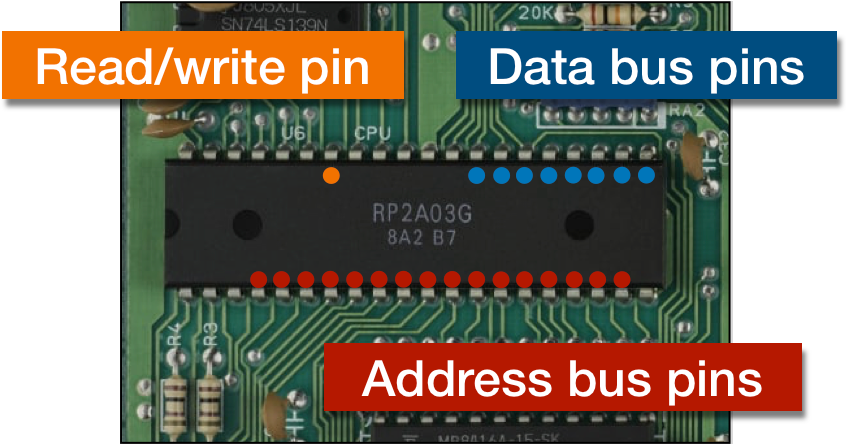
- Data and Address Pins: The 8086 has 16 data pins (D0-D15) and 20 address pins (A0-A19) for data transfer and memory addressing.
- Control Pins: These pins are responsible for controlling the signals that are necessary for coordinating data flow, such as read (RD), write (WR), and interrupt (INTR).
- Clock and Reset Pins: The reset (RESET) pin initializes the microprocessor by wiping out all internal registers, while the clock (CLK) pin synchronizes operations.
- Status and Interrupt Pins: Interrupt pins (S7–S10) manage external interrupts, while status pins (S0-S7) show the state of operations.
Detailed Description of Each Pin
Address/Data Bus Pins
- AD0-AD15 (Multiplexed Address/Data): These sixteen pins have two uses. They carry the address at the start of the bus cycle and transmit data between the CPU and memory or input/output devices.
- A16-A19/S3-S6 (Status and Higher Address Lines): These pins serve as both status signals (S3-S6) and higher address lines (A16-A19), which show what kind of operation the microprocessor is carrying out.
Control and Status Signals
- RD (Read): When the RD pin is present, the microprocessor is carrying out a read operation, which enables the processor to read data from memory or an I/O device.
- WR ( Write): The WR pin indicates that the microprocessor is actively writing data from the processor to an external destination, such as memory or an I/O device.
- ALE (Address Latch Enable): The ALE pin latches the address into external latches. It guarantees that the address is accurate and that external devices can capture it.
- M/IO (Memory/Input-Output): The M/IO pin distinguishes between I/O and memory operations. When it is low, it denotes an I/O operation, and when it is high, it denotes a memory operation.
- DT/R (Data Transmit/Receive): The DT/R pin determines the data flow direction. It shows data transmission from the processor when it is high and data reception when it is low.
- DEN (Data Enable): The DEN pin turns on the data transceivers, enabling data to be sent and received over the data bus and guaranteeing that data flows correctly.
- HOLD: The HOLD pin indicates that an external device is requesting system bus control. In response, the processor relinquishes control, permitting the external device to access the bus.
- HLDA (Hold Acknowledge): The HLDA pin signals that the system bus has been released and the processor has accepted the HOLD request, enabling the external device to assume control.
Interrupt and Direct Memory Access (DMA) Signals
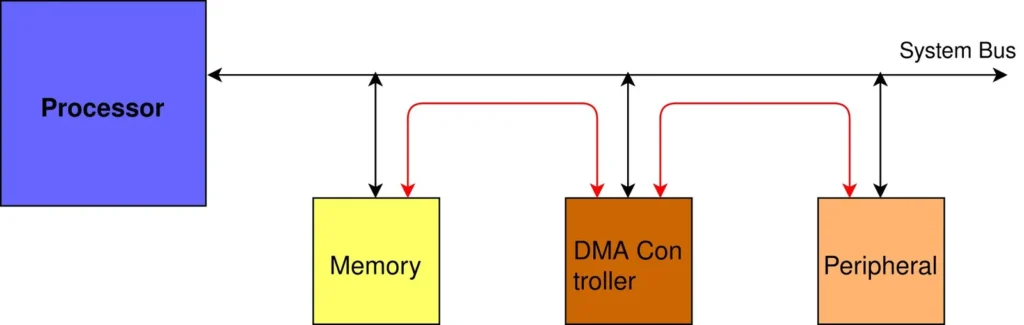
- INTR: The INTR pin serves as a means for peripheral devices to alert the processor to an interrupt, thereby requesting prompt processing.
- INTA (Interrupt Acknowledge): The processor uses the INTA pin to indicate that it will handle an interrupt request and to acknowledge it.
- Non-Maskable Interrupt (NMI): It is possible to disable a non-maskable interrupt, which is a high-priority interrupt that guarantees prompt response when it is triggered by the NMI pin.
- CLK (Clock): This pin supplies the clock signal that keeps the microprocessor’s activities in sync and guarantees that instructions are executed on time.
- RESET: The microprocessor is initialized by the RESET pin, which also ensures a clean start by clearing all internal registers and beginning execution from a predefined memory address.
- TEST: During testing, the TEST pin generates a wait state that permits external devices.
- VCC (Power Supply): The VCC pin provides the required electrical power to ensure proper operation by giving the microprocessor a steady voltage for each internal circuit.
- GND (Ground): This pin completes the electrical circuit by connecting the microprocessor to the ground. It also acts as a reference point for the voltage levels inside the processor.
Mode-Specific Pin Functions
Minimum Mode
When the microprocessor is configured in minimum mode, with the MN/MX pin grounded, it functions as a single processor system. It uses necessary control signals like RD, WR, and ALE for essential operation and handles interrupts like INTR and NMI.
Maximum Mode
When the microprocessor is configured in maximum mode, with the MN/MX pin set high, it functions in a multiprocessor environment. In addition to bus arbitration signals, it uses additional control signals such as DEN, DT/R, and SYNC to enable effective communication between several processors and peripherals.
Practical Applications and Interfacing Examples
The 8086 microprocessor uses the data and address buses to communicate with memory. Address pins send addresses to memory, and data pins receive or send data.
A peripheral device interface uses specific instructions to transfer data between the microprocessor and peripherals like keyboards or printers. The 8086 was used in real-world applications to power early personal computers, handling tasks like data handling, calculations, and screen display.
Conclusion
The 8086 microprocessor’s pin diagram can be understood to determine the essential connections and operations. The chart shows how input-output devices, external memory, and other components interact with address, data, control, and status signals. This knowledge is essential for building and debugging computer systems that use the 8086 processor. Through an understanding of pin configuration, engineers and enthusiasts can efficiently use the microprocessor’s capabilities in a variety of applications, guaranteeing system operation and data processing.
Frequently Asked Questions (FAQ’S)
What is the meaning of ALE?
Enable the address latch. Throughout the microprocessor’s operation, it latches the address on external latches.
Which 8086 pins are used for primary power and ground?
GND (ground) and VCC (power supply) complete the circuit and supply the required electrical power.
What does the RESET pin serve as?
Clearing all internal registers and beginning execution from a known address initializes the microprocessor.
What is the meaning of the RD pin?
The microprocessor retrieves data from external memory or devices when it displays the code RD (Read).